
ORRA / Engineering
The document a factory would actually read.
Concept art does not get quoted. What gets quoted is a layer stack, a component list with real part numbers, a block diagram, a bill of materials and a test plan. Here is what exists, and what is still missing from it.
The stack
Six layers in fifteen millimetres
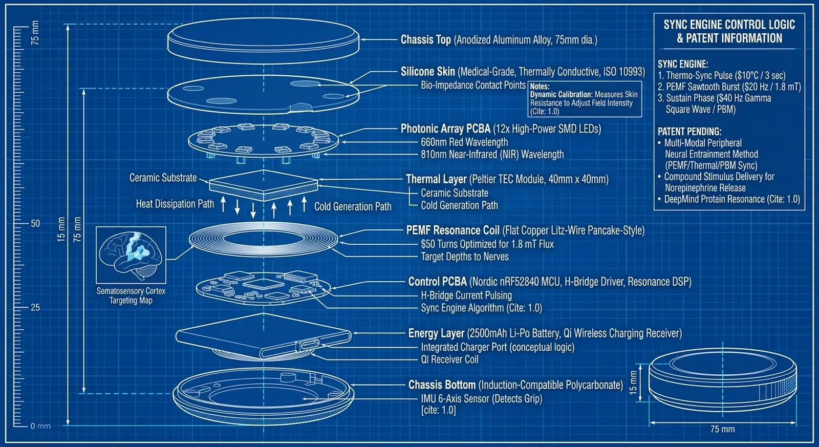
The drawing above is the dimensioned version of the same stack, at 75 mm diameter and 15 mm tall against a millimetre scale. It is a design intent drawing. It is not a schematic, not a board layout and not mechanical CAD, and a factory cannot quote from it — that gap is the single largest item on the list below.
The family as drawn
Nine units, one architecture
Every unit in the family was drawn against the same six layers before any of them was costed. Each product page carries the annotated working sheet it came from; this is the set as it would sit on a shelf.


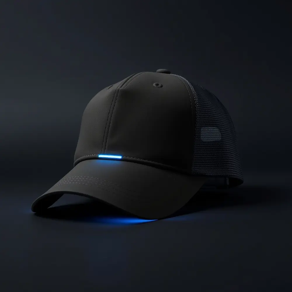


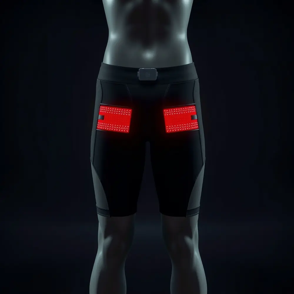
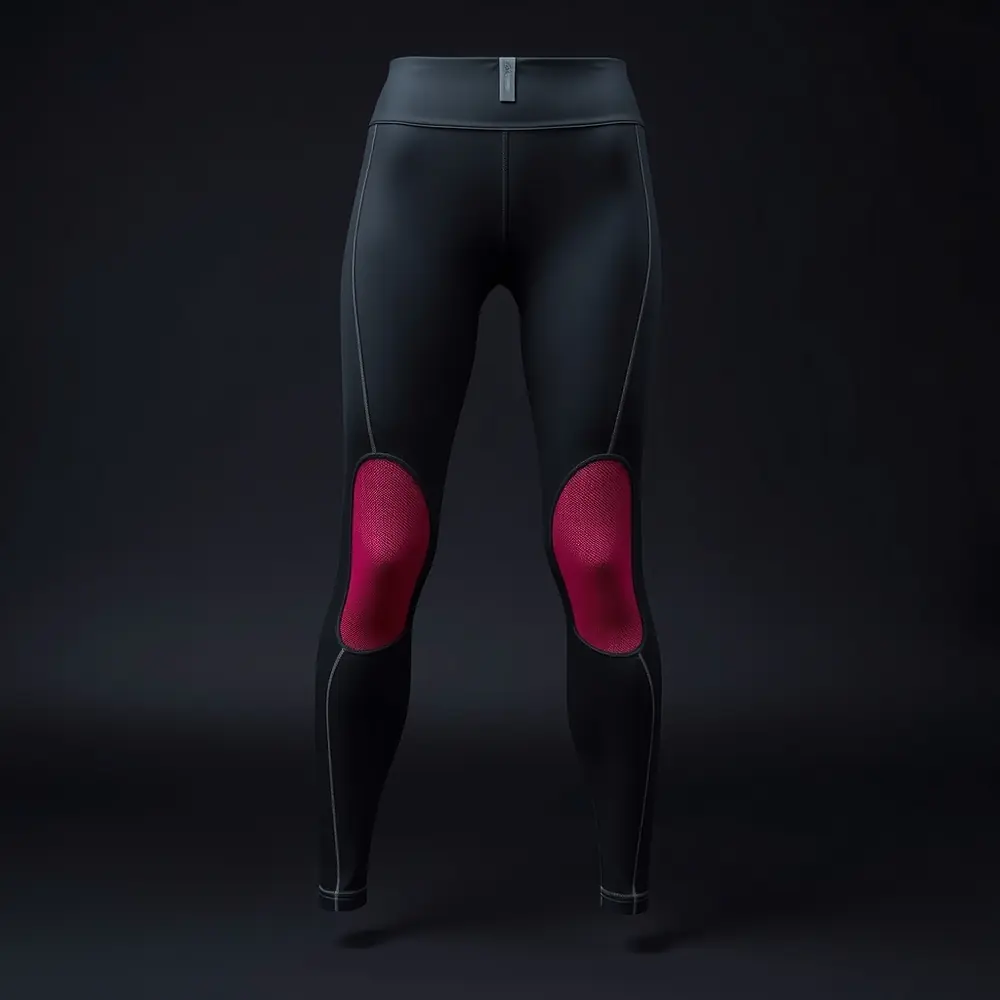

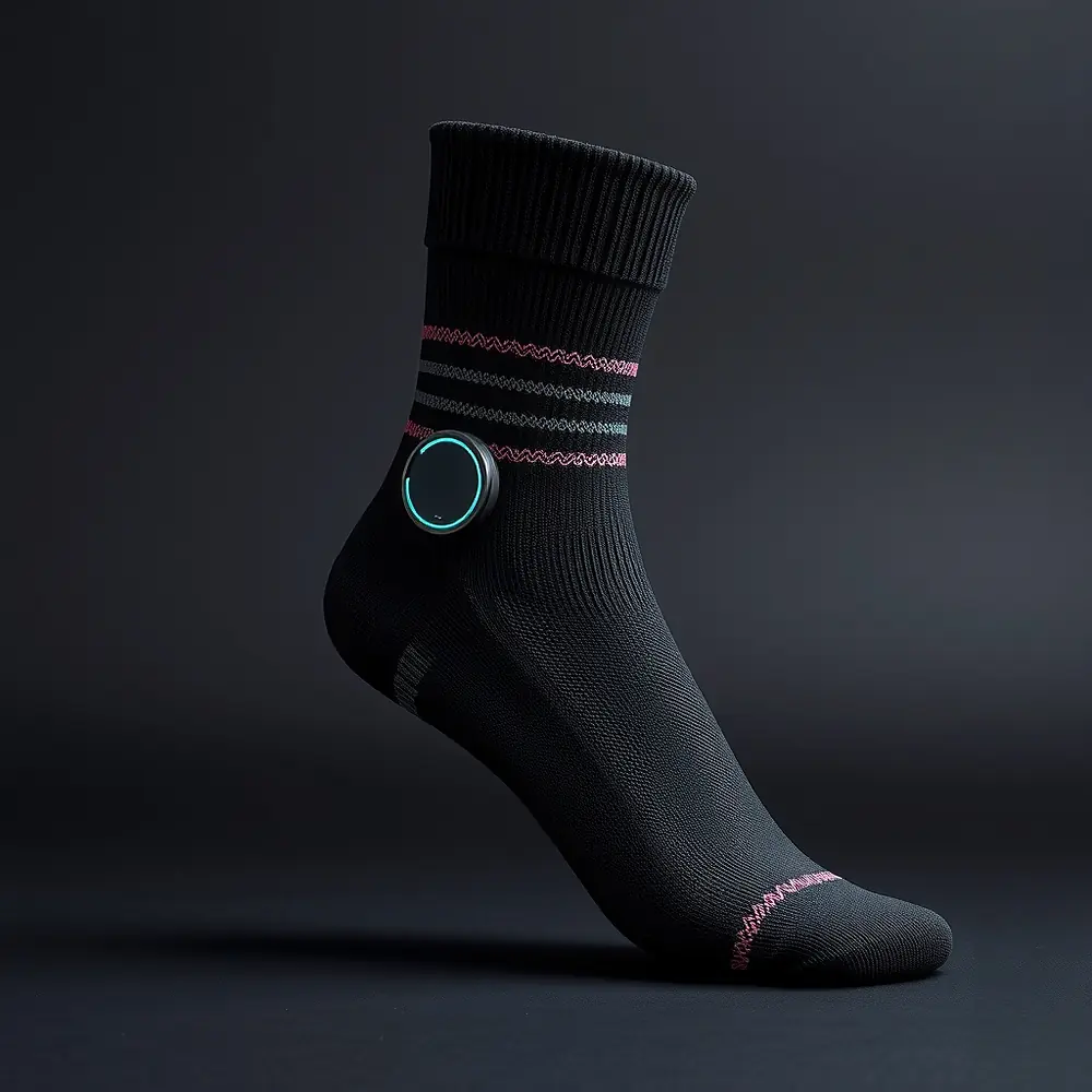
Generated product visualisation, not a photograph. No ORRA unit has been manufactured, so no photograph of one exists. These images were built from the dimensions and components on the concept sheets and are replaced with real photography when the first units are made.

Components
Chosen once, reused across the family
Every active part below is specified by manufacturer part number, not by category. Picking a family standard early means one qualification, one firmware driver and one supply relationship instead of nine.
| Function | Part | Why this one |
|---|---|---|
| MCU and radio | Nordic nRF52840 | Low-power Bluetooth with enough headroom to run the timing loop on-chip. Industry default, so the toolchain and the certification path are well travelled. |
| Thermal driver | TI DRV8833 | Dual H-bridge. Reverses polarity across the Peltier, so one part gives both the cold jolt and the warm face. |
| Coil driver | TI CSD18504Q5A | NexFET MOSFET fast enough to keep a square wave square at 40 Hz into an inductive load. |
| Power management | TI BQ25895 | Handles the burst current the Peltier draws without browning out the MCU. |
| Wireless charging | TI BQ51013B | Qi receiver. The device that started as a question about a charging pad charges on one. |
| Bio-impedance | ADI MAX30001 | Clinical-grade front end. The calibration argument fails with a hobby-grade sensor. |
| Motion | Bosch BMI270 | Detects grip or wear so a session cannot start on a bedside table. |
| Emitters | OSRAM GH CSSRM4.24 (660 nm), SFH 4715S (810 nm) | Binned parts with real radiometric data, which the photobiological safety file will need. |
| Thermoelectric | TEC1-04903 class, 40 x 40 mm | Commodity module. The engineering is in the heat path around it, not in the part. |
| Cell | Custom flat LP604040, 2500 mAh | Flat pack, because 15 mm of total thickness does not allow a cylindrical cell. |
$116 per unit at 100 units, roughly $95 at 500 as the chassis moves off CNC. These are estimates built from component pricing and comparable job costs. No factory has quoted this. The first real number will come back higher, because they always do.
Route to a part
Direct to the factory, not through a distributor
A large distributor adds real value on a programme with a hundred variants and a supply team to manage. On a first run of a hundred units it mostly adds margin and a layer of translation.
The route here is: specify the exact manufacturer part numbers, source them against a component search engine, send the board files and the bill of materials to a turnkey assembly house that buys the parts and ships finished boards, and take the enclosure to CNC and cast silicone rather than paying for injection-mould tooling on a hundred units.
What that route does not buy is engineering judgment. Nobody in that chain will tell you the tooth pitch is wrong or the thermal path is too short. That work stays in-house, which is the reason this page exists rather than a quote request.
| Step | Who does it | What has to be handed over |
|---|---|---|
| Board fabrication and assembly | Turnkey PCBA house | Gerbers, pick-and-place file, costed BOM with approved alternates |
| Enclosure | CNC shop, cast silicone for the skin | STEP files, tolerance and finish notes, an IP-rating target |
| Box build | Same PCBA house | Assembly sequence, torque and adhesive notes, thermal interface spec |
| Test | Factory floor, to our procedure | A pass/fail script per unit: field strength, plate temperature, emitter output, radio |
| Certification | An accredited lab | Golden samples and a full technical construction file |
Test plan
What every unit has to pass before it is boxed
| Test | Criterion |
|---|---|
| Field strength | Measured flux at the contact face within tolerance of 1.8 mT at the rated drive |
| Thermal | Contact face reaches 10 degC within the jolt window; internal face never passes its cut-off |
| Emitter output | Both wavelengths within radiometric tolerance at the contact face |
| Cut-off | Deliberately drive the plate past limit and confirm the hardware watchdog stops it |
| Contact loss | Break the impedance path mid-session and confirm output stops |
| Radio | Bluetooth link and RF output inside the pre-scan envelope |
| Ingress | Sealed to the rated level under a dynamic, not static, test |
| Thermal cycling | A sample from each batch runs the jolt cycle to failure or to the cycle target, and the housing is inspected for micro-fracture |
Alongside the per-unit script, a golden sample defines what a correct unit looks and feels like, so a batch dispute has a reference to point at rather than an argument.
Gaps
What is genuinely not done
- No schematic. A block diagram is not a schematic. Nothing has been drawn at net level.
- No board files. No layout, no stack-up, no Gerbers.
- No mechanical CAD. No STEP files for the chassis, which is what a CNC shop needs before it can quote.
- No firmware. The mode table is a specification, not code.
- No thermal model. The heat path from the Peltier's hot face to the outside is the single biggest unknown in the Core, and it is currently a paragraph rather than a simulation.
- No textile programme. Every worn unit assumes a conductive weave that carries a coil, survives washing and does not break at a flex point. That is its own multi-year development.
Ready to look at the engineering?
The layer stack, the component list with manufacturer part numbers and the mode table are written down. Ask and you get the same document a contract manufacturer would.
See what it would cost
Concept retail against a real bill of materials, with the margin shown rather than implied.
Pricing →Start with the science
Three physical layers, six set points, one calibration baseline. Ninety seconds of reading.
How it works →